Loading...
Hardware Platform
The Transmon Qubit
The most widely used superconducting qubit. Built from a Josephson junction and a capacitor, cooled to fifteen millikelvin, controlled with microwave pulses. This is how IBM, Google, and Rigetti build quantum computers.
Operating Temp15mK
Gate Time10-100ns
~100
~50
Anharmonicity~300
Single-qubit Gate Fidelity~99.9%
History & Origins
From the Cooper pair box to the dominant superconducting qubit architecture.
The transmon qubit was introduced in 2007 by Koch et al. at Yale University [1]J. Koch et al. (2007). Charge-insensitive qubit design derived from the Cooper pair box. Phys. Rev. A 76, 042319., building on decades of superconducting circuit research. It evolved from the Cooper pair box (CPB), the first superconducting qubit demonstrated in 1999 by Nakamura et al. [2]Y. Nakamura et al. (1999). Coherent control of macroscopic quantum states in a single-Cooper-pair box. Nature 398, 786–788.. The CPB encoded quantum information in the number of Cooper pairs on a small island, but suffered from extreme sensitivity to charge noise — random fluctuations in the electrostatic environment that dephased the qubit within microseconds.
In the Cooper pair box, the Hamiltonian is:
where is the dimensionless gate charge. The energy levels depend periodically on , with a charge dispersion of order ~. At the charge degeneracy point , the dispersion is suppressed to ~, but away from this point the qubit dephases rapidly [2]Y. Nakamura et al. (1999). Coherent control of macroscopic quantum states in a single-Cooper-pair box. Nature 398, 786–788..
The key insight of the transmon design was to shunt the Josephson junction with a large capacitor, making the ratio / ≫ 1 (typically 20–100). In this regime, the qubit becomes insensitive to charge noise because the charge dispersion is exponentially suppressed [1]J. Koch et al. (2007). Charge-insensitive qubit design derived from the Cooper pair box. Phys. Rev. A 76, 042319. [4]P. Krantz et al. (2019). A quantum engineer's guide to superconducting qubits. Appl. Phys. Rev. 6, 021318.. The tradeoff is reduced anharmonicity, but the transmon retains enough ( ~ −) to address individual transitions.
In the transmon limit / ≫ 1, charge dispersion is exponentially suppressed:
For the lowest transition , this gives a charge dispersion many orders of magnitude smaller than , making the qubit effectively immune to charge noise while preserving enough anharmonicity for addressable transitions [1]J. Koch et al. (2007). Charge-insensitive qubit design derived from the Cooper pair box. Phys. Rev. A 76, 042319..
1999
Cooper Pair Box
Nakamura et al. demonstrate first superconducting qubit with charge encoding [2]Y. Nakamura et al. (1999). Coherent control of macroscopic quantum states in a single-Cooper-pair box. Nature 398, 786–788.
2007
Transmon Invented
Koch et al. at Yale solve charge noise problem with shunted junction design [1]J. Koch et al. (2007). Charge-insensitive qubit design derived from the Cooper pair box. Phys. Rev. A 76, 042319.
2019–2024
Quantum Advantage
Google claims quantum supremacy [7]F. Arute et al. (Google) (2019). Quantum supremacy using a programmable superconducting processor. Nature 574, 505–510.; IBM scales to 1000+ qubits [10]IBM Quantum (2023). IBM Quantum Heron and Condor processor announcements. IBM Research Blog.
Since its invention, the transmon has become the workhorse of the superconducting quantum computing industry [5]M. H. Devoret & R. J. Schoelkopf (2013). Superconducting circuits for quantum information: An outlook. Science 339, 1169–1174. [4]P. Krantz et al. (2019). A quantum engineer's guide to superconducting qubits. Appl. Phys. Rev. 6, 021318.. IBM, Google, Rigetti, and Amazon Braket all use transmon-based architectures. The design has been refined through generations: the xmon (cross-shaped transmon with direct XY control) [20]R. Barends et al. (2014). Superconducting quantum circuits at the surface code threshold for fault tolerance. Nature 508, 500–503., the fluxonium (higher coherence via large inductance), and the 0- qubit (intrinsic noise protection). Despite these alternatives, the standard transmon remains the most widely deployed due to its simplicity, reproducibility, and the maturity of the surrounding control stack.
The Josephson Junction
A thin insulating barrier between two superconductors. Cooper pairs tunnel through it quantum-mechanically, creating a nonlinear inductor — the heart of every transmon qubit.
In 1962, Brian Josephson predicted that Cooper pairs — bound pairs of electrons in a superconductor — could tunnel through a thin insulating barrier. This effect creates a unique relationship between voltage and phase across the junction:
Where is the critical current and is the phase difference across the junction. This sine relationship makes the Josephson junction a nonlinear inductor — crucial for building a qubit [17]M. H. Devoret (1997). Quantum fluctuations in electrical circuits. Les Houches Session LXIII. [4]P. Krantz et al. (2019). A quantum engineer's guide to superconducting qubits. Appl. Phys. Rev. 6, 021318..
Without nonlinearity, energy levels would be equally spaced (like a harmonic oscillator), making it impossible to selectively address the → transition without also exciting → .
The Josephson energy = / 2e and the charging energy = e² / 2 are the two fundamental energy scales of any superconducting qubit. In a transmon, / ~ 20–100, placing it in the transmon regime where the qubit is insensitive to charge noise but still nonlinear enough for addressable transitions [1]J. Koch et al. (2007). Charge-insensitive qubit design derived from the Cooper pair box. Phys. Rev. A 76, 042319..
The junction is not a simple resistor or capacitor — it is a nonlinear inductor whose inductance depends on the current flowing through it: LJ = / (2e cos ) = LJ0 / cos . This nonlinearity arises from the macroscopic quantum coherence of Cooper pairs tunneling through the insulator [17]M. H. Devoret (1997). Quantum fluctuations in electrical circuits. Les Houches Session LXIII.. When combined with a shunt capacitor, the circuit behaves as an anharmonic oscillator — the quantum analogue of a pendulum with a sinusoidal potential [5]M. H. Devoret & R. J. Schoelkopf (2013). Superconducting circuits for quantum information: An outlook. Science 339, 1169–1174..
When a DC voltage V is applied across the junction, the phase evolves according to the AC Josephson relation:
This means a DC voltage produces an oscillating current at frequency / 2 = 483.6 GHz/V = 0.4836 MHz/μV — the Josephson constant. In a transmon, the junction is voltage-biased near zero, and the phase is the quantum degree of freedom that encodes the qubit state [17]M. H. Devoret (1997). Quantum fluctuations in electrical circuits. Les Houches Session LXIII..
For small phase excursions around the potential minimum, the junction behaves as a harmonic oscillator with the Josephson plasma frequency:
This is approximately the qubit transition frequency. Typical values give / 2 ~ 4–6 GHz, placing the transmon squarely in the microwave regime where standard electronics can drive and read out the qubit [4]P. Krantz et al. (2019). A quantum engineer's guide to superconducting qubits. Appl. Phys. Rev. 6, 021318..
The full dynamics of a Josephson junction, including dissipation and capacitance, are described by the resistively and capacitively shunted junction (RCSJ) model:
In the quantum regime ≫ T, ≫ T, phase and charge become conjugate quantum variables, and the junction becomes a genuine quantum mechanical system — the foundation of all superconducting qubits [17]M. H. Devoret (1997). Quantum fluctuations in electrical circuits. Les Houches Session LXIII..
No bias applied. The junction sits in its ground state with zero net current.
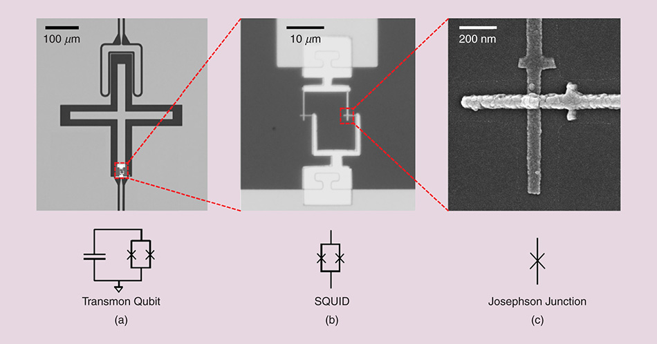
SEM micrograph of a transmon qubit. Left: the full cross-shaped qubit capacitor (100 μm scale). Center: zooming into the SQUID loop where two Josephson junctions sit (10 μm scale). Right: a single Josephson junction formed by the overlap of two aluminum electrodes across a thin oxide barrier (200 nm scale). Below are the corresponding circuit diagrams: (a) transmon qubit, (b) DC-SQUID, (c) single Josephson junction.
0.50 V
5.0 μA
50
What you are seeing: The Josephson junction behaves as a nonlinear inductor governed by two relations. The DC Josephson relation I = sin() says the supercurrent through the junction depends sinusoidally on the phase difference across it. The AC Josephson relation ̇ = 2eV/ says a bias voltage causes the phase to evolve in time.
Top panel — Energy landscape: The curve plots the junction potential E() = − cos(). The red dot shows the junction's current state. With zero voltage it sits at the minimum; with voltage applied it rolls continuously along the cosine washboard.
Middle readouts: The current bar shows the instantaneous supercurrent I = sin(), which oscillates as the phase evolves. The phase readout shows in radians.
Bottom panel — Tunneling: Cooper pairs (bound pairs of electrons) tunnel quantum-mechanically through the thin oxide barrier. The animation visualizes this macroscopic quantum coherence — the phenomenon that makes superconducting qubits possible.
Try this: Set = 0 and watch the dot settle at a potential minimum with zero net current. Then increase — the phase begins to roll, the current oscillates, and Cooper pairs tunnel across the barrier. Raise the barrier thickness to see tunneling become rarer (exponentially suppressed).
The Transmon Energy Landscape
A transmon is a Josephson junction shunted by a large capacitor. The capacitor suppresses charge noise, while the junction's nonlinearity creates unequally spaced energy levels — the key to addressable quantum transitions.
The transmon Hamiltonian combines the Josephson energy and the charging energy :
In the transmon regime, ≫ . This makes the qubit insensitive to charge noise (the "charge dispersion" is exponentially suppressed), at the cost of reduced anharmonicity [1]J. Koch et al. (2007). Charge-insensitive qubit design derived from the Cooper pair box. Phys. Rev. A 76, 042319. [4]P. Krantz et al. (2019). A quantum engineer's guide to superconducting qubits. Appl. Phys. Rev. 6, 021318..
The energy levels are approximately:
The anharmonicity = E12 − E01 ≈ − is what lets us selectively drive → without exciting → . For a typical transmon, ≈ −200 MHz to −300 MHz, while ≈ 5 GHz.
Near the potential minimum, the transmon Hamiltonian can be expanded as a Duffing oscillator — a harmonic oscillator perturbed by a quartic term:
where a† and a are bosonic ladder operators and the anharmonicity = − appears as a self-Kerr nonlinearity. This quartic term shifts each energy level by an amount proportional to n(n−1), creating the unequal spacing essential for selective qubit control [1]J. Koch et al. (2007). Charge-insensitive qubit design derived from the Cooper pair box. Phys. Rev. A 76, 042319..
The coupling between the qubit and a microwave drive depends on the charge matrix element, which sets the Rabi frequency:
A larger / ratio increases the matrix element (faster gates) but decreases anharmonicity (more leakage to ). The transmon design balances these competing requirements at / ~ 20–100 [4]P. Krantz et al. (2019). A quantum engineer's guide to superconducting qubits. Appl. Phys. Rev. 6, 021318..
The transmon qubit frequency is set by the Josephson and charging energies: ≈ √(8) − . Typical values are ~ 10–20 GHz and ~ 0.2–0.3 GHz, giving /2 ~ 4–6 GHz — a microwave frequency that is easy to generate with standard room-temperature electronics [4]P. Krantz et al. (2019). A quantum engineer's guide to superconducting qubits. Appl. Phys. Rev. 6, 021318..
In practice, transmons are operated in the dispersive regime of circuit QED: the qubit is detuned from the readout resonator by = − ≫ g, where g is the qubit-resonator coupling strength (~ 50–200 MHz). This prevents the qubit and resonator from exchanging energy while still allowing the qubit state to shift the resonator frequency — the basis of dispersive readout [3]A. Blais et al. (2021). Circuit quantum electrodynamics. Rev. Mod. Phys. 93, 025005. [16]A. Wallraff et al. (2004). Strong coupling of a single photon to a superconducting qubit using circuit quantum electrodynamics. Nature 431, 162–167..
In the phase basis, the transmon ground-state wavefunction is approximately a Gaussian localized near = 0 with width σ = (2/)1/4 ≪ 1:
The narrow width means phase fluctuations are small, and the qubit state is insensitive to phase noise — another reason the transmon is robust against environmental disturbances [1]J. Koch et al. (2007). Charge-insensitive qubit design derived from the Cooper pair box. Phys. Rev. A 76, 042319..
50
1.00
()
()
()
5.3%
What you are seeing: A transmon qubit is an anharmonic oscillator whose behavior is set by the ratio / . The energy levels panel shows the unequally spaced levels — the key property that lets us address → without accidentally exciting → . The wavefunction panel shows the ground-state probability density |ψ()|² in the phase basis. The Bloch sphere visualizes the qubit state within the / subspace.
Controls: The / slider changes the junction-to-charging-energy ratio. A larger value suppresses charge noise (good) but reduces anharmonicity (bad — leakage to becomes easier). The drive amplitude sets how far the state rotates on the Bloch sphere. Try driving → at low / — the warning banner appears because the → transition is too close in frequency.
Energy Levels
Ground-state |ψ()|²
Fabrication & Materials
How transmon chips are made — from aluminum evaporation to e-beam lithography.
Transmon qubits are fabricated using standard semiconductor processing techniques, which is one reason the technology has scaled so rapidly [4]P. Krantz et al. (2019). A quantum engineer's guide to superconducting qubits. Appl. Phys. Rev. 6, 021318. [5]M. H. Devoret & R. J. Schoelkopf (2013). Superconducting circuits for quantum information: An outlook. Science 339, 1169–1174.. The core materials are aluminum (for the superconducting electrodes and Josephson junctions) and sapphire or silicon (for the substrate). Aluminum becomes superconducting below ~1.2 K and forms a thin, stable oxide layer — the key to the Josephson effect.
The Josephson Junction
The junction is typically made by the Dolan bridge technique or shadow evaporation [4]P. Krantz et al. (2019). A quantum engineer's guide to superconducting qubits. Appl. Phys. Rev. 6, 021318.. A resist mask with an undercut profile is patterned by electron-beam lithography. Aluminum is evaporated from two angles — first one side, then the other after oxidation — forming a thin AlOx barrier (~ 1–2 nm) between two Al layers. The junction area is tiny: roughly 100 × 100 nm², giving critical currents in the range of 10–100 nA.
Where is the critical current, is the superconducting gap of aluminum (~ 180 μeV), and is the normal-state resistance of the junction. Typical values are ~ 10–20 GHz [4]P. Krantz et al. (2019). A quantum engineer's guide to superconducting qubits. Appl. Phys. Rev. 6, 021318..
The critical current is fundamentally linked to the junction's normal-state resistance by the Ambegaokar-Baratoff relation:
For a typical junction with ~ 10–15 kΩ, this gives ~ 10–20 nA and ~ 10–20 GHz, precisely in the transmon regime. This relationship is universal — it depends only on the superconducting gap of aluminum and the junction resistance [4]P. Krantz et al. (2019). A quantum engineer's guide to superconducting qubits. Appl. Phys. Rev. 6, 021318..
The Chip Architecture
A transmon chip contains hundreds to thousands of qubits arranged in a 2D lattice. Each qubit consists of:
- •A cross- or pad-shaped capacitor (area ~ 100–400 μm²) providing the shunt capacitance ~ 50–100 fF
- •A Josephson junction (or junction array) embedded in the capacitor structure
- •A readout resonator (quarter-wave or lumped-element, typically 4–8 GHz) capacitively coupled to the qubit
- •Coupling bus resonators or direct capacitive couplings to neighboring qubits
- •Control lines: XY drive lines for single-qubit gates, Z flux lines for frequency tuning
The total charging energy depends on all capacitances in the circuit:
where ~ 1–5 fF is the junction capacitance, ~ 5–20 fF is the gate capacitance to the control line, and ~ 50–100 fF is the intentional shunt capacitor. The large shunt dominates, suppressing to ~ 0.2–0.3 GHz and making the qubit charge-noise insensitive [4]P. Krantz et al. (2019). A quantum engineer's guide to superconducting qubits. Appl. Phys. Rev. 6, 021318..
Fabrication Process
The typical fabrication flow involves: (1) substrate cleaning and preparation, (2) optical lithography for large-scale features (resonators, control lines), (3) electron-beam lithography for the Josephson junctions, (4) double-angle aluminum evaporation with in-situ oxidation, (5) lift-off, and (6) dicing and wire bonding. The entire process is performed in a cleanroom environment to avoid contamination that would degrade coherence times [4]P. Krantz et al. (2019). A quantum engineer's guide to superconducting qubits. Appl. Phys. Rev. 6, 021318. [6]J. M. Martinis et al. (2005). Decoherence in Josephson qubits from dielectric loss. Phys. Rev. Lett. 95, 210503..
The dominant decoherence mechanism in modern transmons is dielectric loss from two-level systems (TLS) in the oxide layers and substrate interfaces. The participation ratio formalism quantifies how much the electric field overlaps with lossy dielectrics:
A typical sapphire substrate has Q ~ 10⁶–10⁷, while the native oxide on aluminum has Q ~ 10³–10⁴. Minimizing the participation ratio pi of lossy materials — through careful design of the capacitor geometry — is the key to achieving > 100 μs coherence times [6]J. M. Martinis et al. (2005). Decoherence in Josephson qubits from dielectric loss. Phys. Rev. Lett. 95, 210503..
Key fabrication parameters
Substrate
Sapphire / Si
Superconductor
Aluminum
Junction area
Lithography
Optical + e-beam
The Dilution Refrigerator
A transmon qubit must sit at roughly 15 millikelvin — colder than outer space. Achieving this requires a multi-stage cooling system called a dilution refrigerator.
Superconductivity disappears above a few Kelvin. To keep the qubit in its superconducting state and minimize thermal noise, the chip sits at the base of a cryogen-free dilution refrigerator — a closed-loop cooling system that uses the phase separation of helium-3 and helium-4 isotopes to reach temperatures below 10–20 mK, colder than outer space [4]P. Krantz et al. (2019). A quantum engineer's guide to superconducting qubits. Appl. Phys. Rev. 6, 021318. [5]M. H. Devoret & R. J. Schoelkopf (2013). Superconducting circuits for quantum information: An outlook. Science 339, 1169–1174.. These systems are used not only in quantum computing but also in materials science, astrophysics, and fundamental research.
The cooling happens in stages. Each stage removes heat from the stage below it, creating a temperature gradient from room temperature down to the quantum realm. The entire apparatus is roughly the size of a person and costs $500K–$2M.
How the Dilution Unit Works
The heart of the refrigerator is the dilution unit, which provides cooling through the heat of mixing of helium-3 and helium-4. He-3 is a fermion and He-4 is a boson — a fundamental difference that makes this cooling possible. Below about 0.87 K, the mixture separates into two phases: an He-3 rich phase (concentrated) and an He-3 poor phase (dilute). Approaching absolute zero, the concentrated phase becomes nearly pure He-3, while the dilute phase retains about 6.6% He-3 dissolved in superfluid He-4.
The key physics: the enthalpy of He-3 is larger in the dilute phase than in the concentrated phase. This means energy is required to move He-3 atoms across the phase boundary — and that energy is drawn from the surrounding environment, producing cooling. In the mixing chamber, where the phase boundary sits, He-3 is continuously pumped from the concentrated phase into the dilute phase, creating the ultra-low temperatures.
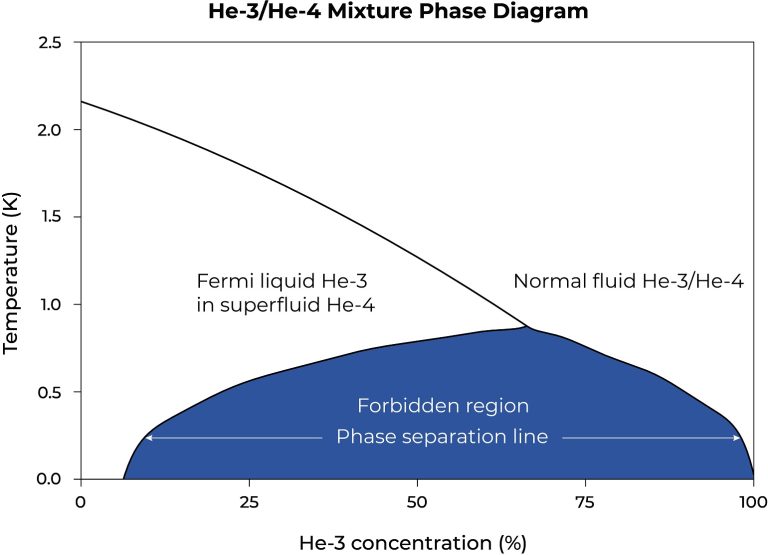
Phase diagram of the He-3/He-4 mixture. Below the phase separation line, the mixture separates into two phases. The dilute phase retains ~6.6% He-3 even at absolute zero.
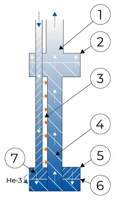
The dilution refrigerator cooling cycle. He-3 circulates through the still, heat exchangers, and mixing chamber, absorbing heat as it crosses the phase boundary.
In steady-state operation, He-3 is circulated by a gas handling system. It enters the dilution unit precooled by the pulse tube cryocooler to about 3 K, passes through the still chamber, and flows down through continuous-flow heat exchangers and step heat exchangers that cool it before it reaches the mixing chamber. From the mixing chamber, He-3 flows back up into the still, where it evaporates and is pumped away. The efficiency of the entire system depends critically on the heat exchangers — the incoming He-3 must be cooled by the outgoing He-3 as much as possible.
The still heater is essential for operation: without heating, the vapor pressure in the still becomes too small for pumps to circulate He-3 effectively. Because He-3 has a higher vapor pressure than He-4, heating the still distills He-3 out of the mixture (the gas phase is ~90% He-3), driving the circulation loop. The available cooling power is directly proportional to the He-3 circulation rate.
Thermal Noise and Shielding
Even at 15 mK, thermal photons can cause errors. The qubit frequency (~ 5 GHz) corresponds to ~ 240 mK, so the thermal occupation is low but not zero. Every microwave line entering the fridge must be heavily filtered and thermalized [4]P. Krantz et al. (2019). A quantum engineer's guide to superconducting qubits. Appl. Phys. Rev. 6, 021318..
The thermal photon occupation at the qubit frequency follows the Bose-Einstein distribution:
At /2 = 5 GHz and T = 15 mK, this gives ≈ 3 × 10⁻⁴. In contrast, at room temperature T = 300 K, the same frequency has ≈ 1,250. The qubit thermal relaxation time is limited by (th) ≈ / , so achieving millikelvin temperatures is essential for preserving quantum information [4]P. Krantz et al. (2019). A quantum engineer's guide to superconducting qubits. Appl. Phys. Rev. 6, 021318..
The microwave lines that carry control and readout signals pass through multiple stages of attenuation and filtering. At each temperature stage, the coaxial cables are thermalized to absorb heat. Near the mixing chamber, eccosorb filters and low-pass filters with cutoff frequencies around 8–10 GHz block high-frequency thermal photons from reaching the qubit. The total attenuation per line can exceed 60 dB, ensuring that the noise temperature at the qubit chip is dominated by the 15 mK environment rather than the 300 K room-temperature electronics [4]P. Krantz et al. (2019). A quantum engineer's guide to superconducting qubits. Appl. Phys. Rev. 6, 021318..
The noise temperature at the qubit after cascading attenuators at multiple stages is:
where A is the total attenuation in dB. With ~ 60 dB of attenuation, the room-temperature noise (300 K) is suppressed by a factor of 10⁶, while the 15 mK environment contribution dominates. Each attenuator must be thermalized to its local stage to ensure the noise is at the bath temperature, not the input temperature [4]P. Krantz et al. (2019). A quantum engineer's guide to superconducting qubits. Appl. Phys. Rev. 6, 021318..
Magnetic shielding is equally critical. The qubit is sensitive to magnetic flux noise, which can shift its frequency via the AC Stark effect and cause dephasing [6]J. M. Martinis et al. (2005). Decoherence in Josephson qubits from dielectric loss. Phys. Rev. Lett. 95, 210503.. Multiple layers of mu-metal and superconducting shields surround the qubit chip, attenuating external magnetic fields by factors of 10⁴–10⁶. Even the Earth's magnetic field (~ 50 μT) must be suppressed to nanotesla levels at the chip.
The magnetic flux sensitivity of a transmon comes from the dependence of the Josephson energy on magnetic flux through the SQUID loop:
where = h/2e ≈ 2.068 × 10⁻¹⁵ Wb is the flux quantum. A flux noise 1/2 ~ 1 μ/√Hz at the qubit frequency shifts the transition by δ ≈ (∂/∂Φ) δΦ, causing pure dephasing with rate ∝ . Multiple layers of mu-metal and superconducting shields attenuate external fields by 10⁴–10⁶ [6]J. M. Martinis et al. (2005). Decoherence in Josephson qubits from dielectric loss. Phys. Rev. Lett. 95, 210503..
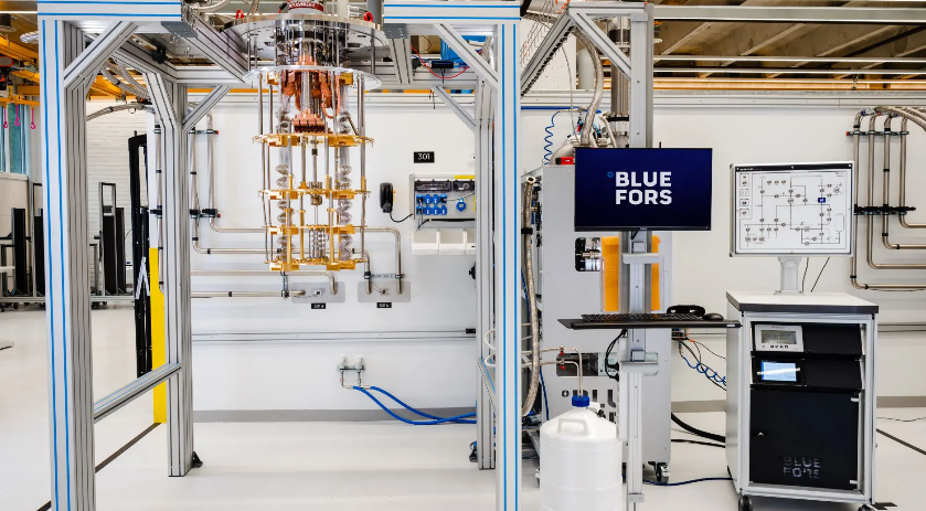
A commercial cryogen-free dilution refrigerator. The vertical stack contains the cooling stages from room temperature down to the millikelvin mixing chamber. The gas handling system and control electronics are on the right.
300 K
Room Temperature
Control electronics, cryogenic amplifiers
50 K
Pulse Tube Stage
Radiation shields, cryogenic filters
4 K
Liquid Helium
Still: He-4 liquefies
1 K
Pot Stage
He-3 / He-4 mixture
100 mK
Cold Plate
Cryogenic filters, coaxial lines
15 mK
Mixing Chamber
The qubit chip lives here
Click a stage on the diagram to see details
What you are seeing: A dilution refrigerator is a multi-stage cooling system that takes the qubit chip from room temperature down to roughly 15 millikelvin — colder than outer space. Each stage removes heat from the one below it, creating a temperature gradient from 300 K → 15 mK.
How it works: The pulse tube stage (50 K) removes most of the heat load. The 4 K stage liquefies helium-4. The pot stage (1 K) begins separating helium-3 and helium-4 isotopes. The cold plate (100 mK) filters microwave signals to protect the qubit from noise. Finally, the mixing chamber (15 mK) is where the helium-3 circulates between concentrated and dilute phases, absorbing heat through the entropy of mixing — the same physics that makes ice cubes melt in your drink, but at temperatures 20,000× colder.
Try this: Click any stage on the left to see its temperature in Celsius and Fahrenheit, the components installed there, and why that stage matters for quantum computing.
Microwave Control
Quantum gates are performed by shining microwave pulses at the qubit. The frequency, amplitude, and shape of each pulse determine which rotation happens on the Bloch sphere.
A transmon qubit behaves like an artificial atom with two primary states: (ground) and (first excited). To perform a quantum gate, we apply a microwave pulse resonant with the transition frequency ≈ 4–6 GHz.
The pulse shape matters. A simple rectangular pulse causes frequency splatter (like a square wave's harmonics). Real systems use shaped pulses — Gaussian, DRAG (Derivative Removal by Adiabatic Gate), or optimal control pulses — to minimize leakage to and reduce spectral noise [4]P. Krantz et al. (2019). A quantum engineer's guide to superconducting qubits. Appl. Phys. Rev. 6, 021318. [20]R. Barends et al. (2014). Superconducting quantum circuits at the surface code threshold for fault tolerance. Nature 508, 500–503..
In the rotating frame at the drive frequency ωd, the interaction Hamiltonian is:
where ΩR = 2eV0⟨1|n̂/ is the Rabi frequency, σ± are the qubit raising and lowering operators, and δ = ωd − is the detuning. On resonance (δ = 0), the qubit undergoes Rabi oscillations:
A -pulse requires ΩR t = , while a /2-pulse creates an equal superposition ( + )/√2 [4]P. Krantz et al. (2019). A quantum engineer's guide to superconducting qubits. Appl. Phys. Rev. 6, 021318..
Off resonance, the generalized Rabi formula gives:
To minimize leakage to and reduce spectral noise, shaped pulses are used. The DRAG (Derivative Removal by Adiabatic Gate) pulse modifies the quadratures to cancel the → transition:
where Ω(t) = Ω0 exp[−(t−t0)²/2σ²] is a Gaussian envelope and is the qubit anharmonicity. DRAG pulses have achieved single-qubit gate fidelities above 99.99% [20]R. Barends et al. (2014). Superconducting quantum circuits at the surface code threshold for fault tolerance. Nature 508, 500–503..
A pulse with area θ rotates the qubit around the X-axis of the Bloch sphere by angle θ. A -pulse (θ = ) flips to . A /2-pulse creates an equal superposition.
Two-qubit gates (like CZ or iSWAP) are more complex — they require tuning qubits into resonance or exploiting the coupling between them via a shared bus resonator [4]P. Krantz et al. (2019). A quantum engineer's guide to superconducting qubits. Appl. Phys. Rev. 6, 021318. [3]A. Blais et al. (2021). Circuit quantum electrodynamics. Rev. Mod. Phys. 93, 025005..
Control Electronics Chain
The microwave control chain spans from room temperature to the qubit chip. At room temperature, arbitrary waveform generators (AWGs) produce baseband I/Q signals with bandwidths of ~ 500 MHz. These are upconverted to the qubit frequency (~ 5 GHz) using IQ mixers driven by local oscillators. The microwave signal then passes through amplifiers, attenuators, and filters before entering the dilution refrigerator [4]P. Krantz et al. (2019). A quantum engineer's guide to superconducting qubits. Appl. Phys. Rev. 6, 021318..
The full qubit-drive interaction in the lab frame is Hd = ΩRσxcos(ωdt). Transforming to the rotating frame and applying the rotating wave approximation (RWA), we drop the rapidly oscillating terms at ωd + :
The RWA is valid when ΩR ≪ , which is always satisfied in transmon systems where ΩR/2 ~ 1–100 MHz and /2 ~ 5 GHz [4]P. Krantz et al. (2019). A quantum engineer's guide to superconducting qubits. Appl. Phys. Rev. 6, 021318..
Inside the fridge, the signal is attenuated at each temperature stage (300 K → 50 K → 4 K → 15 mK) to thermalize the noise. At the mixing chamber, the signal is further attenuated by ~ 20 dB before reaching the qubit. The total chain has ~ 60–80 dB of attenuation, ensuring that the noise temperature at the qubit is dominated by the 15 mK environment [4]P. Krantz et al. (2019). A quantum engineer's guide to superconducting qubits. Appl. Phys. Rev. 6, 021318..
For readout, the reflected signal from the resonator travels back up the fridge, is amplified by a high-electron-mobility transistor (HEMT) amplifier at 4 K, and then by a low-noise amplifier at room temperature. The signal is downconverted, digitized, and demodulated to extract the I and Q quadratures, which reveal the qubit state [14]E. Jeffrey et al. (2014). Fast accurate state measurement with superconducting qubits. Phys. Rev. Lett. 112, 190504..
100 ns
1
Resonant
What you are seeing: Quantum gates are performed by applying microwave pulses resonant with the → transition. The pulse shape determines how cleanly the qubit rotates on the Bloch sphere. A square pulse acts like a hard step — fast but spectrally broad, causing leakage to . A Gaussian pulse is smoother and reduces leakage. DRAG (Derivative Removal by Adiabatic Gate) adds a derivative correction that cancels the → transition, achieving the highest fidelity.
Controls: Duration sets how long the pulse lasts (shorter = faster but more spectral broadening). Amplitude controls the rotation angle — a -pulse flips → , a /2-pulse creates an equal superposition. Detuning shifts the drive frequency away from resonance, causing the state to precess around the Z-axis. Click Show leakage to see how much population escapes to the second excited state for each pulse shape.
Pulse Shape
Main pulse
Bloch Sphere
State: (north pole)
State Readout
|0⟩100.0%
|1⟩0.0%
State vector
= 1.000 + 0.000
How We Read the Qubit
You cannot measure a qubit directly without destroying its superposition. Instead, transmon systems use dispersive readout: the qubit shifts the frequency of a coupled resonator, and we probe the resonator.
The qubit is capacitively coupled to a microwave resonator. When the qubit is in , the resonator has one frequency. When the qubit is in , the resonator shifts to a slightly different frequency. This is the dispersive shift [3]A. Blais et al. (2021). Circuit quantum electrodynamics. Rev. Mod. Phys. 93, 025005. [13]D. I. Schuster et al. (2007). Resolving photon number states in a superconducting circuit. Nature 445, 515–518..
The full Jaynes-Cummings Hamiltonian for a qubit coupled to a resonator is:
where a†, a are resonator ladder operators and g is the coupling strength. In the dispersive regime || = | − | ≫ g, we apply a unitary transformation to eliminate the direct coupling. The resulting dispersive Hamiltonian is [3]A. Blais et al. (2021). Circuit quantum electrodynamics. Rev. Mod. Phys. 93, 025005.:
The dispersive shift arises from virtual exchange of photons between the qubit and resonator. For a transmon with anharmonicity = −:
Typical values g/2 ~ 50–200 MHz, /2 ~ 500–2,000 MHz, and /2 ~ −200 MHz give /2 ~ 0.5–2 MHz. This small shift is enough to distinguish and when integrated over many photons [3]A. Blais et al. (2021). Circuit quantum electrodynamics. Rev. Mod. Phys. 93, 025005. [14]E. Jeffrey et al. (2014). Fast accurate state measurement with superconducting qubits. Phys. Rev. Lett. 112, 190504..
To measure the qubit, we send a weak microwave tone at the resonator frequency and measure the phase of the reflected signal. The phase depends on whether the resonator was shifted — revealing the qubit state without directly interacting with it [14]E. Jeffrey et al. (2014). Fast accurate state measurement with superconducting qubits. Phys. Rev. Lett. 112, 190504..
The key insight: the measurement is projective. Even though the probe is weak, after many photons the qubit collapses to or . The resonator acts as an amplifier — the tiny qubit state creates a macroscopic shift in the resonator field that classical electronics can detect [3]A. Blais et al. (2021). Circuit quantum electrodynamics. Rev. Mod. Phys. 93, 025005..
In practice, the readout signal is digitized and plotted in the IQ plane. Two blobs form: one for and one for . The separation between blobs determines readout fidelity [14]E. Jeffrey et al. (2014). Fast accurate state measurement with superconducting qubits. Phys. Rev. Lett. 112, 190504..
The signal-to-noise ratio of the measurement determines the readout fidelity:
where n ~ 10–100 is the number of readout photons, is the resonator linewidth, and ℱ is the single-shot fidelity. A SNR of ~ 3 already gives ℱ > 99%. State-of-the-art systems achieve ℱ ~ 99.5–99.8% in ~ 1 μs [14]E. Jeffrey et al. (2014). Fast accurate state measurement with superconducting qubits. Phys. Rev. Lett. 112, 190504..
Typical readout parameters are: resonator frequency /2 ~ 6–8 GHz, qubit-resonator coupling g/2 ~ 50–200 MHz, and dispersive shift /2 ~ 0.5–2 MHz. The readout pulse contains nphotons ~ 10–100 photons, and the integration time is ~ 1–5 μs. State-of-the-art systems achieve single-shot readout fidelities of 99.5%–99.8% [14]E. Jeffrey et al. (2014). Fast accurate state measurement with superconducting qubits. Phys. Rev. Lett. 112, 190504..
The dispersive interaction arises from second-order perturbation theory in the Jaynes-Cummings Hamiltonian. When the qubit and resonator are far detuned ( = − ≫ g), the energy levels shift proportionally to the number of photons in the resonator and the qubit state. This is the quantum AC Stark effect — the qubit frequency shifts by 2n where n is the photon number, and the resonator frequency shifts by ± depending on whether the qubit is in or [3]A. Blais et al. (2021). Circuit quantum electrodynamics. Rev. Mod. Phys. 93, 025005. [13]D. I. Schuster et al. (2007). Resolving photon number states in a superconducting circuit. Nature 445, 515–518..
The measurement process itself introduces measurement-induced dephasing. Photon number fluctuations in the resonator cause the qubit frequency to fluctuate via the AC Stark shift δω = 2δn, leading to:
where n̄ is the mean photon number and the second term accounts for thermal photons in the resonator. Fast readout ( ≫ ) minimizes this backaction. After the resonator photons decay, the qubit is projected into or with probability given by the Born rule [3]A. Blais et al. (2021). Circuit quantum electrodynamics. Rev. Mod. Phys. 93, 025005..
Qubit
Power50
Shots
0
Fidelity
0.0%
Resonator Response
IQ Plane
Circuit Diagram
Click Measure to send readout pulse
What you are seeing: In dispersive readout, the qubit is coupled to a microwave resonator. The qubit state shifts the resonator frequency by 2 — this is the dispersive shift. We never measure the qubit directly; instead we send a weak microwave tone at the resonator and look at the phase of the reflected signal. The resonator response panel shows how the transmission peak moves depending on whether the qubit is (blue) or (red). The dashed line is the probe frequency.
IQ plane: Each measurement produces a point in the IQ (in-phase/quadrature) plane. After many shots, the points cluster into two blobs — one for and one for . The fidelity tells us how well we can distinguish the two states.
Controls: Toggle the qubit state to see the resonator shift. The power slider controls readout strength: low power gives fuzzy, overlapping blobs (low fidelity), while high power separates them but increases measurement backaction — the act of measuring can accidentally flip the qubit state. Try ~ 50–70% power for the best readout fidelity. Click Measure to collect IQ points and watch the fidelity converge.
Sweet spot:
Quantum Error Correction
From noisy physical qubits to reliable logical qubits — the path to fault-tolerant quantum computing.
Transmon qubits are noisy. With ~ 100 μs and two-qubit gate fidelities of ~ 99.5%, every operation has a small but non-negligible error probability [4]P. Krantz et al. (2019). A quantum engineer's guide to superconducting qubits. Appl. Phys. Rev. 6, 021318. [20]R. Barends et al. (2014). Superconducting quantum circuits at the surface code threshold for fault tolerance. Nature 508, 500–503.. For useful quantum computation, we need logical qubits — encoded states that are protected against errors through quantum error correction (QEC).
The dominant noise in transmon qubits is well described by the depolarizing channel, which applies Pauli errors uniformly:
For a single-qubit gate with fidelity 99.9%, the error probability is p ≈ 10⁻³ per gate. Over a circuit with 10⁶ gates, uncorrected errors would overwhelm the computation. The surface code corrects these errors by encoding one logical qubit into 2d² − 1 physical qubits [9]A. G. Fowler et al. (2012). Surface codes: Towards practical large-scale quantum computation. Phys. Rev. A 86, 032324..
The Surface Code
The leading QEC scheme for transmon architectures is the surface code, a 2D topological code where data qubits are arranged on a square lattice and ancilla qubits (measurement qubits) sit between them [9]A. G. Fowler et al. (2012). Surface codes: Towards practical large-scale quantum computation. Phys. Rev. A 86, 032324.. The code detects X and Z errors by measuring stabilizers — products of Pauli operators on neighboring qubits.
Distance-d surface code
Encodes 1 logical qubit into d² physical qubits. Can correct up to ⌊(d−1)/2⌋ arbitrary errors [9]A. G. Fowler et al. (2012). Surface codes: Towards practical large-scale quantum computation. Phys. Rev. A 86, 032324..
Threshold condition
Logical error rate decreases with code distance only if physical error rate is below the threshold (~ 1%) [9]A. G. Fowler et al. (2012). Surface codes: Towards practical large-scale quantum computation. Phys. Rev. A 86, 032324..
A distance-3 surface code uses 17 qubits (9 data + 8 ancilla) and can correct any single error. A distance-5 code uses 49 qubits and corrects up to 2 errors. To achieve logical error rates of 10⁻¹⁰ (needed for Shor's algorithm), estimates suggest distances of 27–41 may be required — meaning roughly 1,000–3,000 physical qubits per logical qubit [9]A. G. Fowler et al. (2012). Surface codes: Towards practical large-scale quantum computation. Phys. Rev. A 86, 032324..
In the surface code, data qubits sit on the vertices of a checkerboard while measure qubits sit at the center of each square. These measure qubits perform stabilizer measurements — they tell us whether the surrounding data qubits are all the same (no error) or different (error detected), without ever revealing the actual state of any individual data qubit. Dark blue plaquettes check for bit-flip (X) errors; light blue plaquettes check for phase-flip (Z) errors.
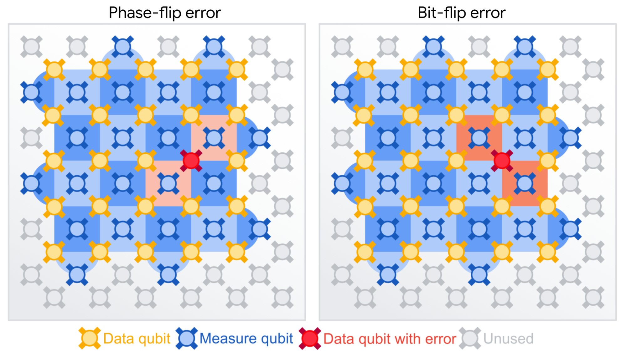
Surface-code QEC on a checkerboard lattice. Left: A phase-flip error triggers the two nearest Z-type stabilizers (light red). Right: A bit-flip error triggers the two nearest X-type stabilizers (dark red). The decoder uses these syndrome patterns to locate and correct the error without measuring the data qubits directly.
For a surface code of distance d, the X and Z stabilizers on the bulk plaquettes and vertices commute with the logical operators and have eigenvalues ±1. Any single-qubit Pauli error anticommutes with at least two adjacent stabilizers, creating a detectable syndrome pattern. The minimum-weight perfect matching (MWPM) decoder then finds the most likely error chain connecting the syndrome defects [9]A. G. Fowler et al. (2012). Surface codes: Towards practical large-scale quantum computation. Phys. Rev. A 86, 032324..
Below-Threshold Error Correction
In December 2024, Google Quantum AI announced Willow, a 105-qubit transmon processor that demonstrated below-threshold QEC for the first time [8]Google Quantum AI (2024). Quantum error correction below the surface code threshold. Nature.. They showed that as they scaled from a distance-3 to distance-5 to distance-7 surface code, the logical error rate decreased — the hallmark of a code operating below threshold. The distance-7 code achieved a logical error rate of 0.143% per cycle, meaning the logical qubit outperformed the individual physical qubits.
This is a watershed moment because it proves that QEC can work in practice, not just in theory. However, the logical error rate is still far too high for useful algorithms. The next milestone is demonstrating a logical qubit with a lifetime longer than any physical qubit — expected in the coming years [8]Google Quantum AI (2024). Quantum error correction below the surface code threshold. Nature..
The hallmark of below-threshold QEC is that the logical error rate decreases exponentially with code distance:
where p is the physical error rate, pth ~ 1% is the threshold, and d is the code distance. Google Willow demonstrated this scaling: the logical error rate decreased from ~ 0.6% (distance-3) to ~ 0.3% (distance-5) to 0.143% (distance-7), confirming operation below threshold. Projecting this trend, a distance-27 surface code would achieve pL ~ 10⁻¹⁰, sufficient for factoring large integers with Shor's algorithm [8]Google Quantum AI (2024). Quantum error correction below the surface code threshold. Nature. [9]A. G. Fowler et al. (2012). Surface codes: Towards practical large-scale quantum computation. Phys. Rev. A 86, 032324..
IBM's Roadmap
IBM has taken a different approach, focusing on scaling physical qubit count while gradually improving error rates. Their Heron processor (133 qubits, announced 2023) achieves two-qubit gate fidelities of ~ 99.7% [10]IBM Quantum (2023). IBM Quantum Heron and Condor processor announcements. IBM Research Blog.. Their Condor chip (1,121 qubits, 2023) demonstrated that million-qubit-scale fabrication is possible, though with lower individual qubit performance [10]IBM Quantum (2023). IBM Quantum Heron and Condor processor announcements. IBM Research Blog..
IBM's strategy involves the heavy-hex lattice — a modified hexagonal connectivity pattern that reduces crosstalk between neighboring qubits while maintaining the 2D geometry needed for surface codes. They project achieving 100,000+ physical qubits by 2033, which with current surface-code overhead estimates would yield roughly 100–200 logical qubits [10]IBM Quantum (2023). IBM Quantum Heron and Condor processor announcements. IBM Research Blog..
The overhead to run useful algorithms is formidable. The total number of physical qubits scales as:
where k ~ 2 accounts for ancilla qubits in the surface code, d ~ 27–41 is the required code distance, and Nlogical is the number of logical qubits. For Shor's algorithm factoring RSA-2048, Nlogical ~ 4,000. Recent estimates center on Nphysical ~ 2 × 10⁷ physical transmon qubits (Gidney & Ekerå), though earlier estimates have ranged from 10⁶–10⁸ [9]A. G. Fowler et al. (2012). Surface codes: Towards practical large-scale quantum computation. Phys. Rev. A 86, 032324. [10]IBM Quantum (2023). IBM Quantum Heron and Condor processor announcements. IBM Research Blog..
Physical vs logical qubit requirements
Current state (2024)~ 1,000 physical qubits
First logical qubit~ 1,000 physical qubits
Useful chemistry simulation~ 10,000 logical qubits
Breaking RSA-2048~ 4,000 logical qubits
Total physical qubits needed~ 2 × 10⁷
Video Resources
Curated talks and explainers on superconducting qubits, from first principles to the latest breakthroughs.
The Map of Superconductivity
~25 minA comprehensive tour of superconducting qubits: from the physics of Cooper pairs and Josephson junctions to the engineering challenges of building a quantum computer.
Quantum Computing with Superconducting Qubits
~55 minAlexandre Blais delivers an in-depth lecture on superconducting qubit architectures, circuit QED, and the path toward fault-tolerant quantum computing.
Quantum Computers, explained with MKBHD
~18 minA fun, accessible stroll through how superconducting quantum computers work — from qubits and cryogenics to why they need to be colder than deep space.
Quantum Computing Expert Explains One Concept in 5 Levels
~20 minA quantum scientist explains superconducting qubits to five different audiences — from a child to a fellow expert — in this WIRED classic.
Who Is Building It
Transmon qubits power the largest and best-funded quantum computing programs in the world.
IBM
Condor: 1,121 qubits (2023)
Superconducting, full-stack
Willow: below-threshold QEC (2024)
Quantum supremacy, error correction
Rigetti
Ankaa-3: 84 qubits
Hybrid classical-quantum
Alice & Bob
Cat qubits (alternative)
Autonomous error correction
Strengths
- •Fast gate operations (~10–100 ns) enable many operations within coherence time
- •Mature fabrication using standard semiconductor lithography
- •Strong industry investment (IBM, Google, AWS, Baidu) drives rapid improvement
- •Well-developed control electronics and software stacks (Qiskit, Cirq, QuTiP)
- •Demonstrated quantum advantage and below-threshold error correction
Limitations
- •Short coherence times (T₁ ~ 100 μs) require fast gates and frequent error correction
- •Nearest-neighbor connectivity limits algorithm efficiency without SWAP overhead
- •Requires dilution refrigerators ($500K–$2M) and complex cryogenic infrastructure
- •Manufacturing variation means every qubit is slightly different — requires individual calibration
- •Two-qubit gate fidelity still below 99.9%, requiring many physical qubits per logical qubit
References
Key papers and reviews for further reading on transmon qubits and superconducting quantum computing.
[1]
J. Koch et al., Charge-insensitive qubit design derived from the Cooper pair box, Phys. Rev. A 76, 042319 (2007).
[2]
Y. Nakamura et al., Coherent control of macroscopic quantum states in a single-Cooper-pair box, Nature 398, 786–788 (1999).
[3]
A. Blais et al., Circuit quantum electrodynamics, Rev. Mod. Phys. 93, 025005 (2021).
[4]
P. Krantz et al., A quantum engineer's guide to superconducting qubits, Appl. Phys. Rev. 6, 021318 (2019).
[5]
M. H. Devoret & R. J. Schoelkopf, Superconducting circuits for quantum information: An outlook, Science 339, 1169–1174 (2013).
[6]
J. M. Martinis et al., Decoherence in Josephson qubits from dielectric loss, Phys. Rev. Lett. 95, 210503 (2005).
[7]
F. Arute et al. (Google), Quantum supremacy using a programmable superconducting processor, Nature 574, 505–510 (2019).
[8]
Google Quantum AI, Quantum error correction below the surface code threshold, Nature (2024).
[9]
A. G. Fowler et al., Surface codes: Towards practical large-scale quantum computation, Phys. Rev. A 86, 032324 (2012).
[10]
IBM Quantum, IBM Quantum Heron and Condor processor announcements, IBM Research Blog (2023).
[11]
J. R. McClean et al., Barren plateaus in quantum neural network training landscapes, Nat. Commun. 9, 4812 (2018).
[12]
M. H. Michael et al., New class of quantum error-correcting codes for a bosonic mode, Phys. Rev. X 6, 031006 (2016).
[13]
D. I. Schuster et al., Resolving photon number states in a superconducting circuit, Nature 445, 515–518 (2007).
[14]
E. Jeffrey et al., Fast accurate state measurement with superconducting qubits, Phys. Rev. Lett. 112, 190504 (2014).
[15]
C. Rigetti et al., Superconducting qubit in a waveguide cavity with a coherence time approaching 0.1 ms, Phys. Rev. B 86, 100506 (2012).
[16]
A. Wallraff et al., Strong coupling of a single photon to a superconducting qubit using circuit quantum electrodynamics, Nature 431, 162–167 (2004).
[17]
M. H. Devoret, Quantum fluctuations in electrical circuits, Les Houches Session LXIII (1997).
[18]
D. Vion et al., Manipulating the quantum state of an electrical circuit, Science 296, 886–889 (2002).
[19]
J. M. Gambetta et al., Investigating the limits of superconducting quantum processors, IBM Research (2017).
[20]
R. Barends et al., Superconducting quantum circuits at the surface code threshold for fault tolerance, Nature 508, 500–503 (2014).
Want to see how it compares?
Each hardware platform makes different tradeoffs. See how transmon qubits stack up against trapped ions, neutral atoms, and photonic systems.
Browse All Platforms